Chapel Field Christian Schools
One of the advantages of programming with the Arduino platform is that you can often see immediate results from your code. We're going to create a program that causes LEDs to blink, both on the board and on a separate breadboard.
Connect your Arduino to your computer and open the Arduino IDE. If it does not automatically open an empty sketch (program) then go to the File menu and select New. Make sure you have the correct port selected.
Raise your hand and have Mr. Olinda verify this checkpoint.
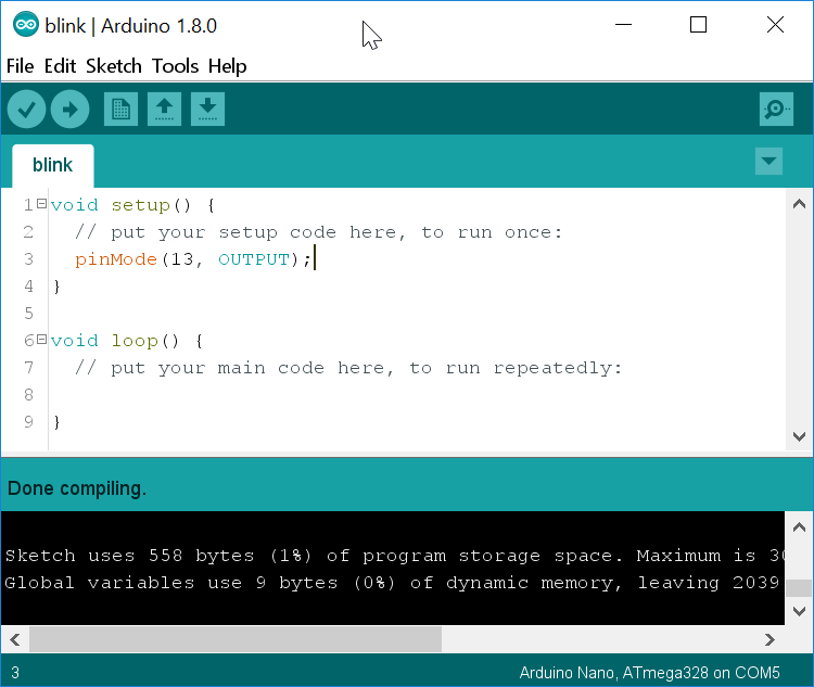
For the program to work, you need to designate one pin as an output pin. The Arduino Uno has a built-in LED attached to pin 13, which is what we will use for now. On line three of your empty program, press Tab and type:
pinMode(13, OUTPUT);This tells the board to set pin 13 to output. Go to the Tools menu and choose Auto Format. Then verify your code to make sure you haven't made any syntax errors. At this point your code won't do anything, so do not upload it yet. Just save it as blink in your cspProjects/arduino folder. Then add and commit it to version control.
What other mode do you think you can set pins to?
Raise your hand and have Mr. Olinda verify this checkpoint.
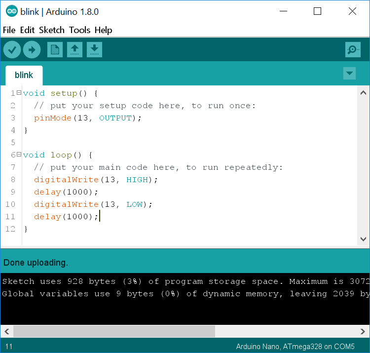
Now let's add the code that will run continuously as long as your Arduino is powered on. Go to line eight and press Tab. Then type:
digitalWrite(13, HIGH);
delay(1000);
digitalWrite(13, LOW);
delay(1000);
Go to the Tools menu and choose Auto Format. Then verify your code to make sure you haven't made any syntax errors. Save it, and then add and commit it to version control. Then upload it and see if the orange LED blinks on and off. If so, you've entered the code correctly. If not, go back and check each line.
What part or parts of your code do you think turns on the light? What part or parts turns it off? What part or parts control the duration of the blink? What unit do you think is used to measure time?
Raise your hand and have Mr. Olinda verify this checkpoint.
The way your program works right now, your LED is on for one second and off for one second. Modify it so that it is on for one second and off for two. The amount of time an LED is on during one cycle is called the duty cycle. So a duty cycle of 50% means that the light is on half the duration of a cycle. Try at least three other combinations of timings. Be prepared to demonstrate changing the timings for Mr. Olinda and express them both in seconds as well as duty cycles.
Raise your hand and have Mr. Olinda verify this checkpoint.
Now that you know how to adjust the timing of the lights, add extra lines of code to turn the light on and off in different patterns. You must create a pattern that uses at least four ON/OFF pairs, and each pair must be different.
Raise your hand and have Mr. Olinda verify this checkpoint.
Go ahead and add comments on each line of code, explaining what you think each line does. Comments are preceded by // so that the compiler knows they're not supposed to be code. Add the comments on the same line as the code they explain.
Raise your hand and have Mr. Olinda verify this checkpoint.
Take a minute to review the following video and and charts so that you have an idea of how to identify resistors by color code. Right-click an image and view it individually to get a closer look.
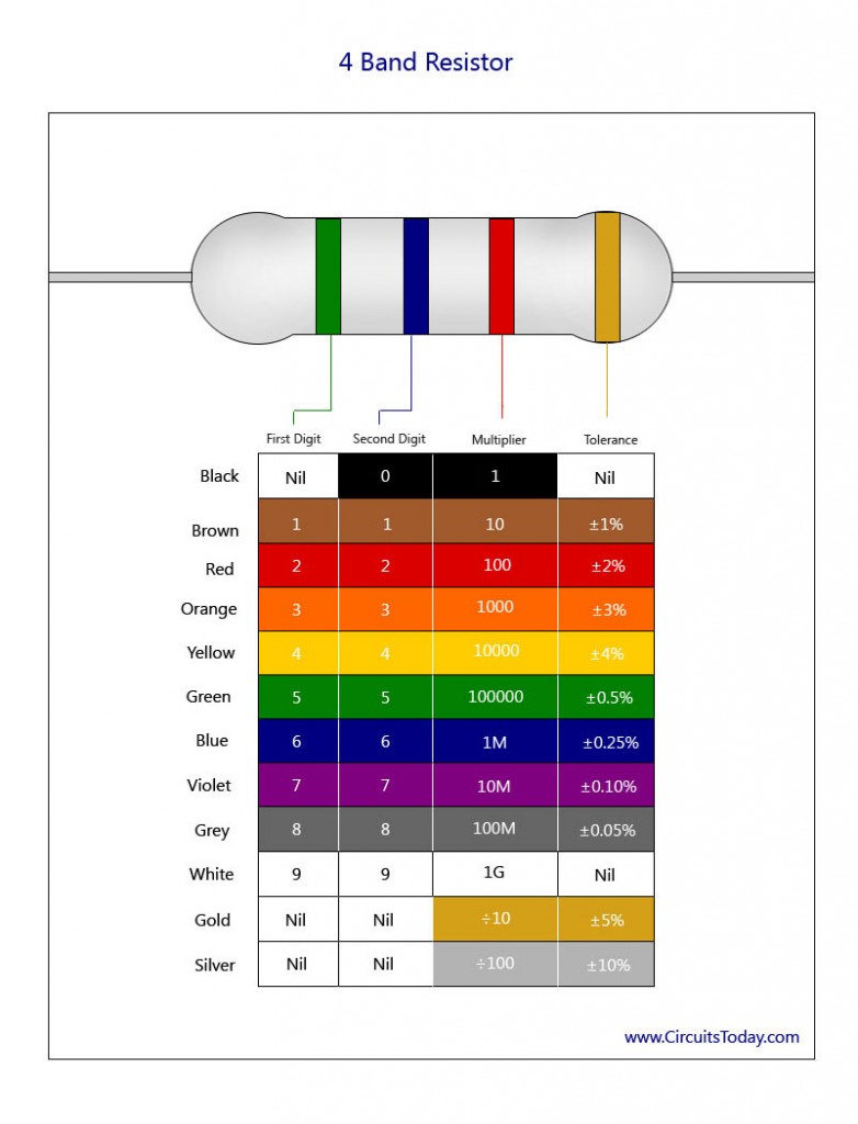
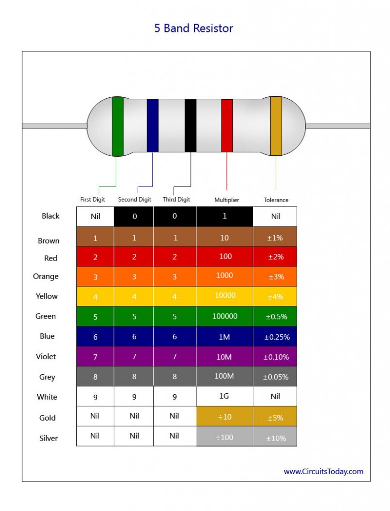
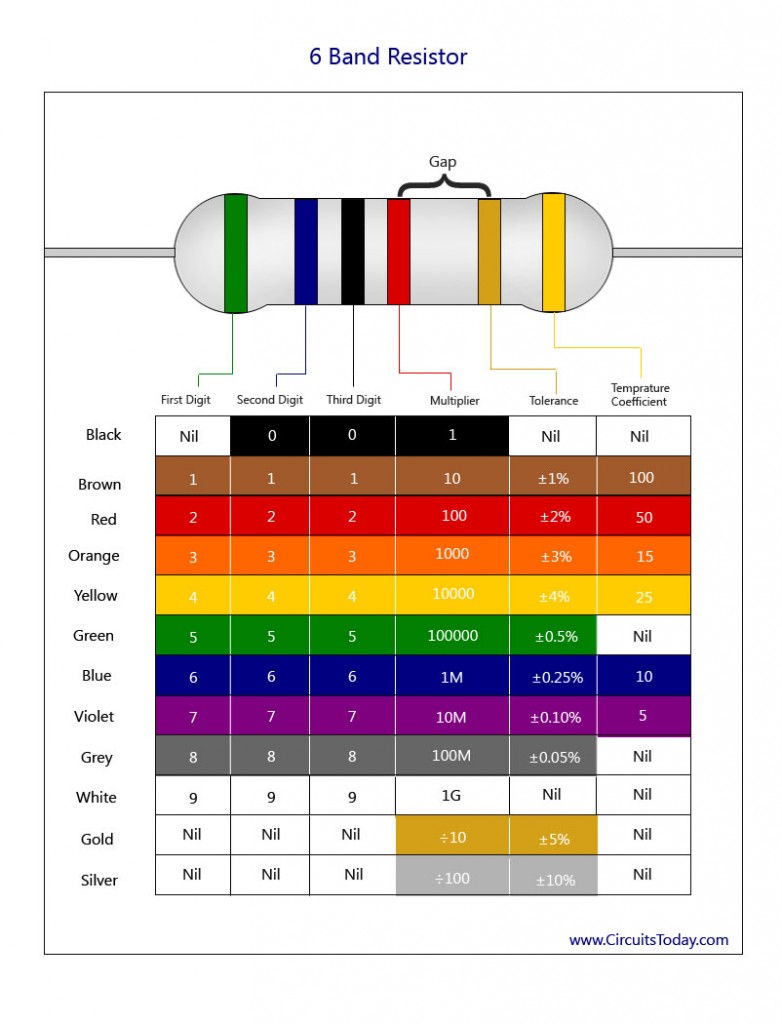
Now we are going to modify the program to turn an external LED on and off. Get a breadboard, two wires, a 1K resistor (black, red, and gold stripes), and a red LED. Breadboards are small, rectangular pieces of plastic with holes in them where you can quickly add and remove wires and other parts to try out different circuits. The wires will carry the current from the board to the LED, and the resistor simply protects the LED from overheating.
Then, unplug and set up your Arduino to match the diagram below. Make sure you use exactly the same pins as the diagram. Notice that one of the pins on the LED is longer. That pin is bent in the diagram.
If you plug your Arduino back in, you'll notice it does not do anything new. Go ahead and edit your code to make the external LED blink. Once it does, save your code, and add and commit it to version control.
Raise your hand and have Mr. Olinda verify this checkpoint.